Adder full nor gate truth logic table diagram using number minimum implementing fa required Adder circuit diagram basic gates using truth table Digital logic design: full adder circuit
2 bit half adder truth table - deliveryvlero
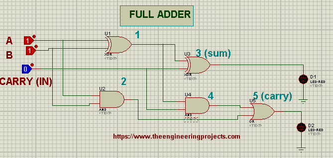
Full adder
Full adder equation
Adder bit implementation gates nand full diagram only addFull adder circuit diagram using logic gates Full adder circuit diagram using logic gatesFull adder : circuit diagram, truth table, equations & verilog code.
Half adder logic diagram and truth table / obe assignment: digitalAdder circuit full logic using digital boolean implementation function diagram implement Full adderWhat is half adder and full adder circuit?.

Adder gates edupointbd boolean
Adder circuit (half adder, full adder and binary adder)Full adder circuit – how it works Adder full half circuit carry ripple bit schematic diagram gate truth table delay electronics doubt xor without representation shown singleFull adder : circuit diagram, truth table, equations & verilog code.
Full adder circuit diagram using nand gatesFull adder circuit diagram Additionneur complet en logique numérique – part 1 – stacklimaHow to build a full adder.

Full adder circuit diagram using basic gates
Boolean algebra4 bit adder subtractor circuit diagram Full adder circuit using basic gatesFull adder circuit diagram using basic gates.
2 bit half adder truth tableFull adder circuit sum carry logic circuits combinational using electronics expression boolean implementation both tutorial two simplified implemented Full adder equationFull adder circuit diagram with logic ic.

Full adder circuit table diagram truth gates verilog using basic
Adder logic projectiot123 binary outputs .
.